My first thought on reading Hackaday’s ESP-SDR can now transmit was that my RTL-SDR could transmit now. It can’t; it only receives. The transmitter in the article is the ESP32 itself: new firmware drives its Wi-Fi radio sample by sample, so it sends whatever you hand it.
The ESP32-S3 in the article’s demo is the same chip that runs my fan and weather gateway, and I wanted to see the transmit side work with what was already on my desk. The catch: the ESP32 transmits at 2.4 GHz, and the only receiver I have stops at 1.77 GHz.
Listening above the dongle’s range
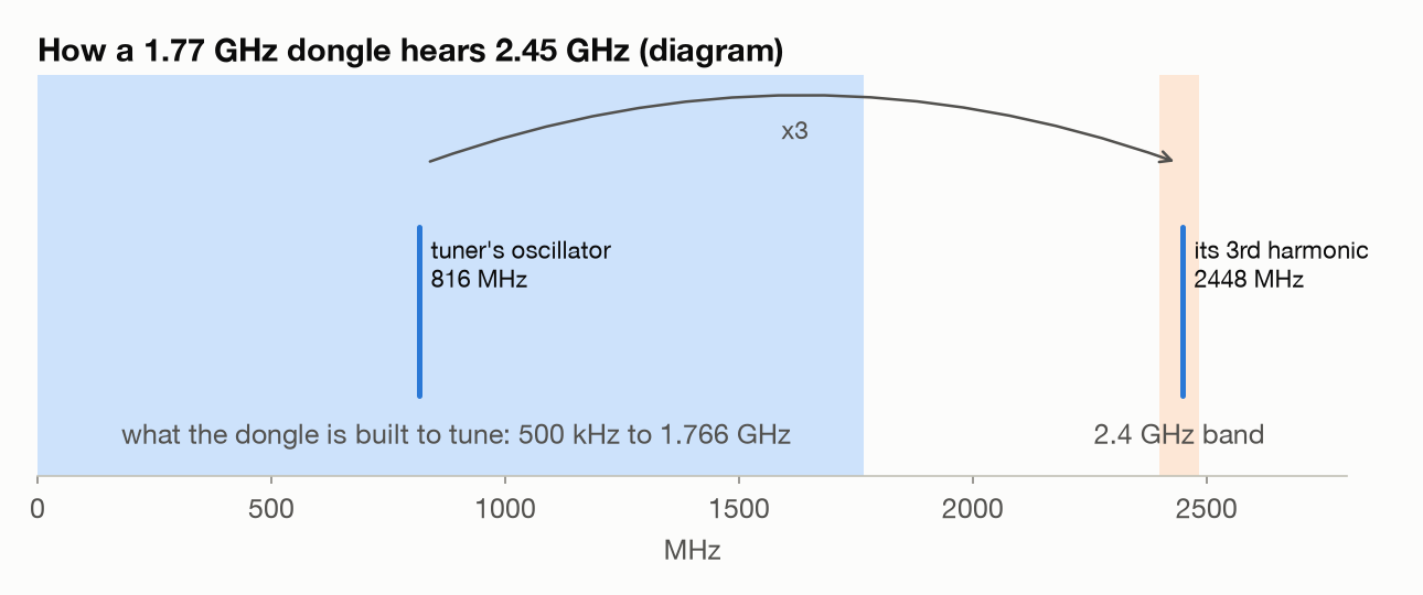
The RTL-SDR’s tuner works by mixing the antenna signal with its own oscillator. That mixer is driven hard, so besides the oscillator itself it also mixes with the oscillator’s odd harmonics, much more weakly. Tune the dongle to 814 MHz and its oscillator sits near 816 MHz; three times that is 2448 MHz, and with the tuner’s 1.8 MHz IF on top, the dongle ends up hearing 2450 MHz. A transmitter on the same desk is strong enough to make up for the loss.
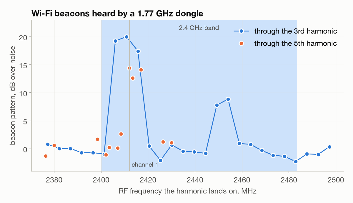
Before transmitting anything, Claude checked the idea on the Wi-Fi around the apartment. Access points send a beacon every 102.4 ms, a rhythm nothing at 800 MHz has, so it stepped the tuning so the third harmonic swept 2.37 to 2.49 GHz and looked for that 9.77 Hz pattern in the received power, after checking the detector on synthetic data first. Channel 1 came in 17 to 20 dB over the noise through the third harmonic, and 12 to 14 dB through the fifth (tuned near 480 MHz instead). Every tuning that landed outside the band read about zero.
How the tuning maps
At 2.4 MS/s, librtlsdr sets the R828D’s IF to 1.815 MHz (bandwidth code) and puts the oscillator at the tuned frequency plus the IF (source). Both harmonics fit RF = n × tuned + 4 × IF, so to look at f through the third harmonic, tune to (f − 7.26 MHz) / 3:
rtl_sdr -f 814263300 -s 2400000 -g 49.6 -n 19200000 s3.cu8 # 2450.05 MHz, 8 s
A dry run with the Flipper
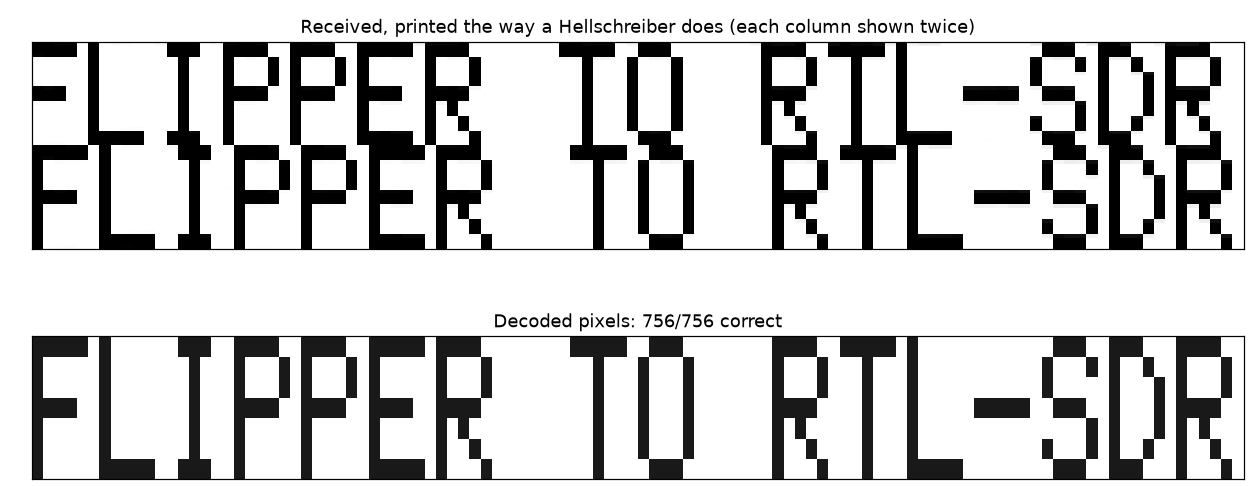
Before borrowing the gateway, the Flipper Zero stood in for the ESP32. The article’s demo uses Hellschreiber, a 1920s teleprinter mode that draws text as columns of pixels, each pixel sent as the carrier on or off for about 4 ms. The receiver prints the columns as a strip, twice over, so a timing slip can’t cut letters in half. Claude wrote an encoder that turns text into a Flipper raw file, and a decoder for the dongle. The Flipper sent “FLIPPER TO RTL-SDR” at 915 MHz, well away from 433.92 MHz so my fan and the gateway never saw it, and the dongle read all 756 pixels.
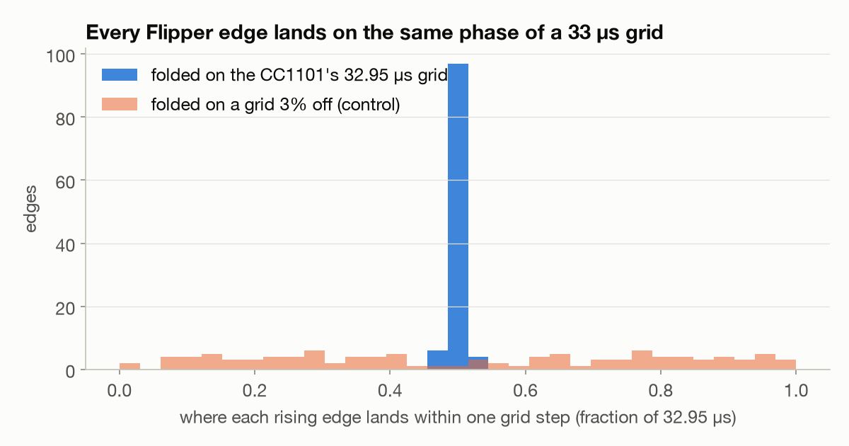
The recording showed something about the Flipper’s CC1101 radio too. Its on/off edges were scattered by about 10 µs around where the file put them, which looked like jitter until we folded them onto a grid. In this mode the CC1101 samples its data pin at eight times the programmed data rate (datasheet, section 27.1), and the Flipper’s OOK preset sets 3.79 kBd, so every edge snaps to a 32.95 µs grid. All 214 edges land on the same phase of it:
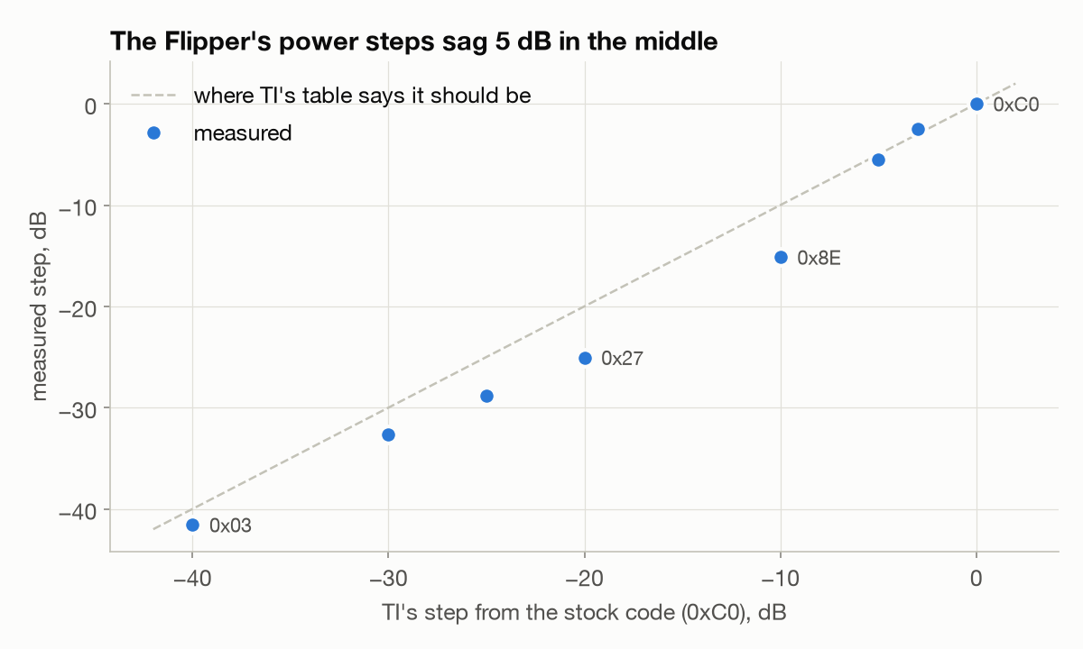
Two more things fell out while the Flipper was transmitting. Its carrier sat about 5 kHz high at 915 MHz, a +5 ppm crystal, and one register write (FSCTRL0, the CC1101’s frequency offset, 1.587 kHz per step) brought it within 0.2 kHz. And its power steps don’t match TI’s table in the middle. Sending each PATABLE code at or below the stock power and measuring the received level, the codes TI rates at 0 and −10 dBm came out 5 dB lower. A control at three receiver gains says that’s the Flipper, not the dongle.
Calibrating the dongle first
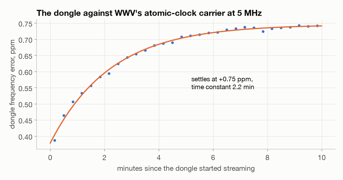
To trust a frequency error on someone else’s crystal, I needed the dongle’s own. WWV’s 5 MHz carrier comes off an atomic clock, so Claude recorded it for ten minutes from a cold start. The dongle reads 0.38 ppm fast when it’s cold and settles at 0.75 ppm fast, with a 2.2-minute time constant. The crystal numbers in this post are corrected for it.
The ESP32 transmits
flowchart LR
  A["Mac\ntext to I/Q samples"] -->|"USB"| B["ESP32-S3\nESP-SDR"]
  B -->|"2.45 GHz"| C["RTL-SDR V4 at 814 MHz\nhearing 2.45 GHz\nthrough its 3rd harmonic"]
  C -->|"USB"| D["Mac\nHellschreiber decoder"]
I unplugged the Waveshare ESP32-S3-ETH from PoE, plugged it into the Mac and set it next to the Flipper. Before flashing anything, Claude read the whole 16 MB flash back to the Mac and checked it against the chip region by region, so the gateway could come back exactly as it was. The board turned out to be wired to the S3’s own USB port, which the SDR firmware needs, and ESP-SDR’s build for the XIAO ESP32S3 ran on it unchanged.
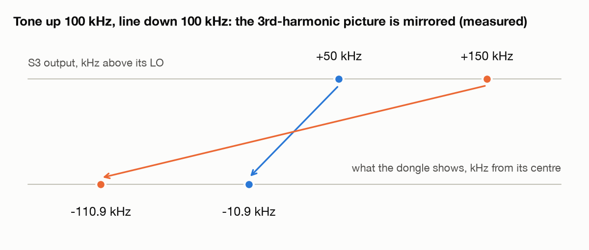
First a plain tone, 50 kHz above the S3’s oscillator, at its weakest power step. It came in 30 dB over the noise through the dongle’s third harmonic. Moving the tone up 100 kHz moved the dongle’s line down 100 kHz, so the picture comes out mirrored, which the harmonic model predicted: the third harmonic picks up the opposite sideband from normal reception. The tone also put the S3’s crystal at +5.2 ppm.
Then Hellschreiber. Claude turned the text into a file of I/Q samples at
250 kS/s, and ESP-SDR’s esdr_usb streamed it over USB to the S3, which played
it out of its Wi-Fi radio’s DAC at 2.45 GHz, on the weakest power step again.
This is what the dongle saw on the air:
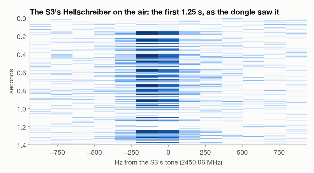
The first message, “ESP32 TO RTL-SDR”, came through 672 of 672 pixels. Then I asked for “derek.engineer” (the font is upper case only):
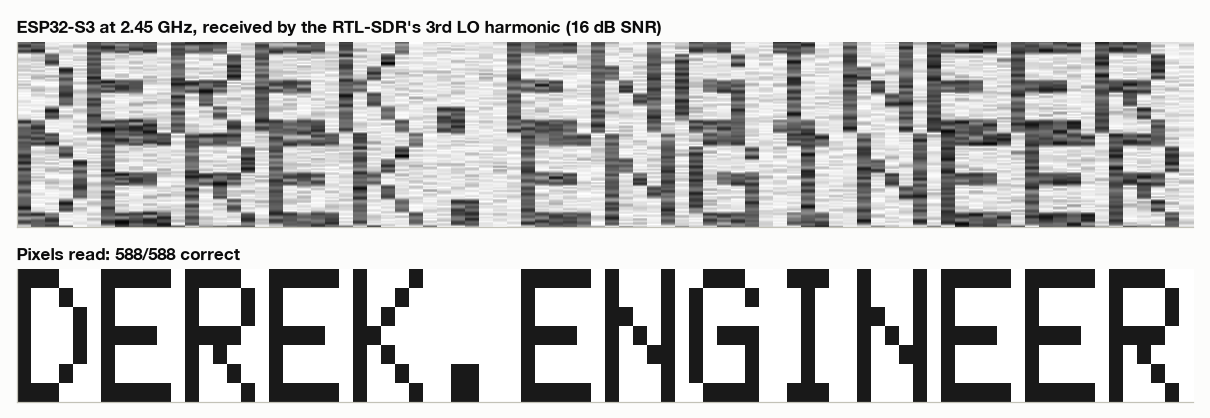
588 of 588 pixels, 16 dB SNR. ESP-SDR receives too: at 2412 MHz, the S3 itself picked up the same channel 1 beacons the dongle heard through its harmonic.
How clean the transmitter is
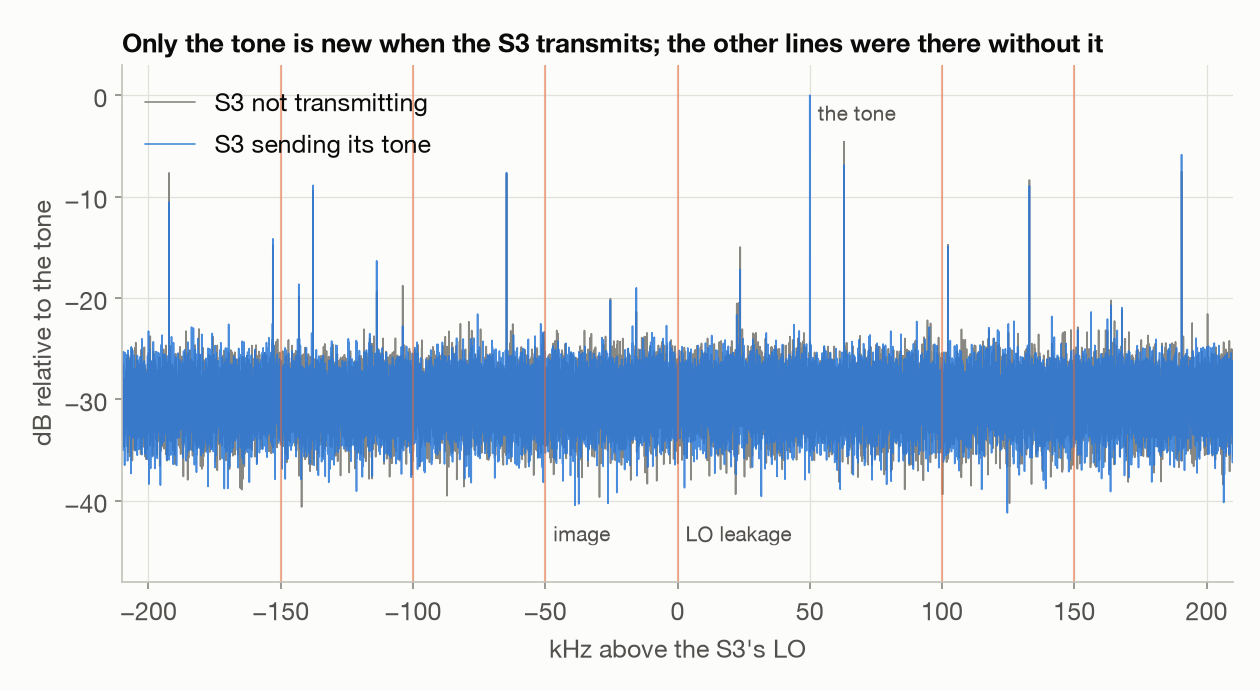
A transmitter asked for one tone also leaks a little of its oscillator, and a mirror image of the tone from I/Q imbalance. Comparing the spectrum with the S3 sending its tone against the same spectrum with the S3 off, only the tone is new. The leftover oscillator, the image and the products further out are all at least 25 dB down. Copies of the tone 250 kHz away, which stretching 250 kS/s up to the DAC’s 40 MS/s leaves behind, didn’t show either: at least 23 dB down. That’s as far as this measurement can see at the weakest power step, not a spec. (The painting below shows those copies are real; for a tone this close to the middle they’re predicted 24 dB down, right at that limit.)
Painting the spectrum
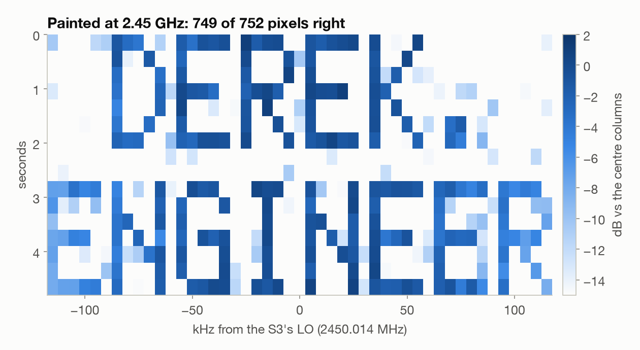
Four days later I wanted a harder test than one tone switching on and off. Spectrum painting draws a picture in the waterfall: every pixel column gets its own tone, and each row of the picture is a slice of time. Claude laid out “DEREK.” over “ENGINEER” on a 5 kHz grid, 47 columns wide, so the text fills 230 kHz of the S3’s 250 kHz band with up to 29 tones on at once, 0.3 s per row. The file opens with a pilot tone, so the receiver can find the S3’s frequency and the start, and a comb of all 46 columns at once to measure the band. Same weakest power step, same third-harmonic trick. ESP-SDR reported no dropped samples and no underruns over the 10.6 seconds.
The dongle read 749 of 752 pixels in the first run and 746 in a second. Each pixel here is its tone’s power, measured over its 0.3 s row:
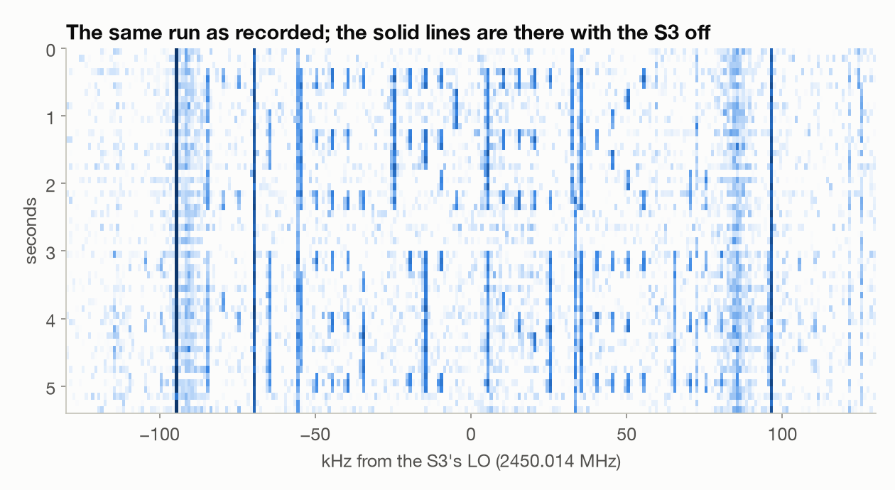
And this is the same run as a plain waterfall, straight from the recording:
The outer letters come out fainter, and that’s the S3, not the dongle. ESP-SDR takes 250 kS/s over USB and stretches it to the DAC’s 40 MS/s by drawing straight lines between samples (source). That’s cheap, and it has a known price: the band droops toward its edges, 6.5 dB down at ±115 kHz. The comb matched that prediction within 0.6 to 0.8 dB rms in both runs:
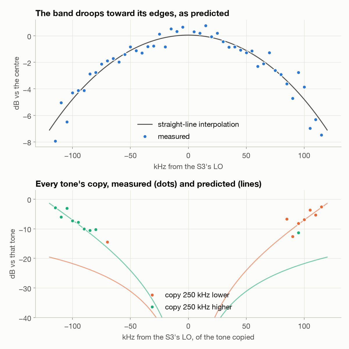
The other half of the price is copies. Straight-line interpolation leaves a copy of everything 250 kHz to each side. Near the middle of the band they’re tiny, but near the edges they’re almost as strong as the original. To make that visible, the S3 painted one E on its own at the top edge of the band, 95 to 115 kHz, where it gets more power per tone than the full text. Its copy turned up at −155 to −135 kHz, pixel for pixel and the right way round (an I/Q image would be mirrored), 2 to 9 dB below the original and within about 1 dB of the prediction column by column:
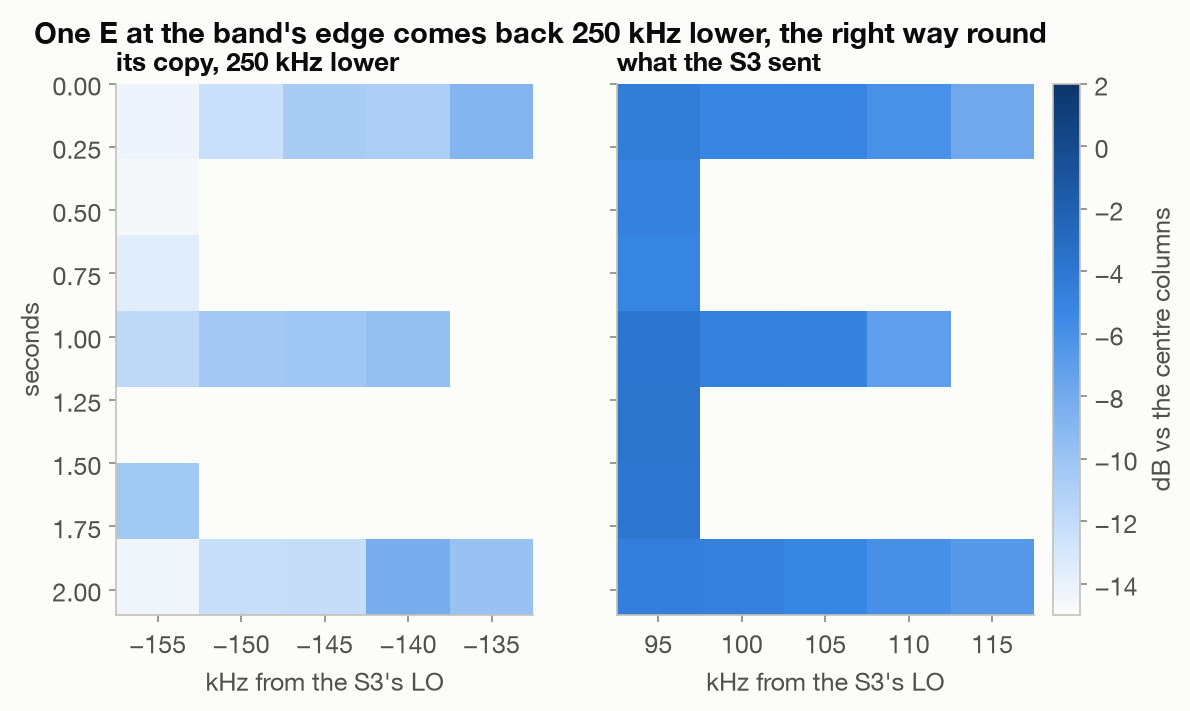
So at 250 kS/s, keep the signal within about ±50 kHz of the centre, where the droop is about a decibel and the copies are at least 24 dB down.
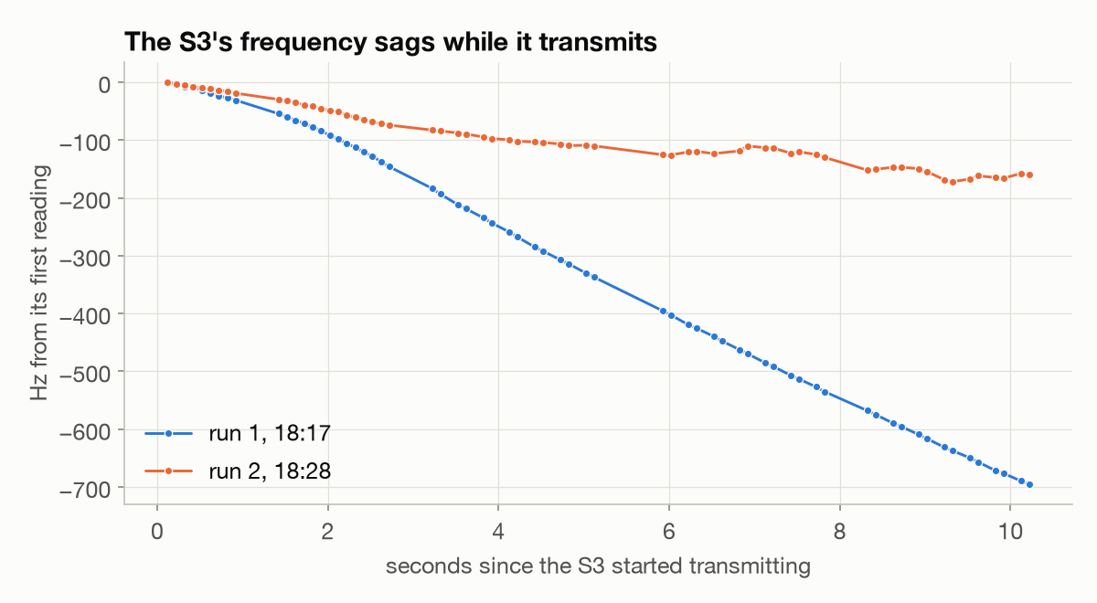
The runs showed one thing I didn’t expect: the S3’s frequency sags while it transmits. In the first run it fell almost 700 Hz in 10 seconds (0.28 ppm), in the second about 160 Hz. Hellschreiber doesn’t care, but anything narrowband would have to track it, and the analysis here had to (below). My guess is the board warming up, but I didn’t measure that.
The pilot put the S3’s I/Q image 32 dB down and its leftover oscillator below 29 dB, in line with Oct 14.
How the receiver reads it
Each pixel is one tone, measured with one spectrum per 0.3 s row (0.24 s of it, 4.2 Hz bins), against the comb’s level for that column scaled to the picture’s amplitude: lit above half of it, dark below. The receiver first follows the S3’s drift in 0.1 s windows (the offset that puts the most power on the tones that window should carry), fits a smoothing spline, takes it out, and refines in 0.25 s windows; what’s left is 0.5 Hz rms. The tone grid also allows for the S3’s sample clock, 5.1 to 5.8 ppm fast in these runs. The copies’ levels against the originals match the prediction, which says the dongle is flat to about a decibel across these frequencies, so the droop is the S3’s.
python3 esp-sdr/make_paint_iq.py                                      # paint_s3.cs8, 10.65 s at 250 kS/s
esdr_usb -f 2450e6 -r 250e3 -b 8 -G 0 -i paint_s3.cs8 -t 10.65 tx      # options before tx
rtl_sdr -f 814096667 -s 2400000 -g 49.6 -n 33600000 paint.cu8           # 2449.55 MHz through the 3rd harmonic
What went wrong
esdr_usb tx -f 2450e6 -G 0 -i fileignored every option aftertx. On macOS,getoptstops at the first argument that isn’t an option, so the first attempt sent a plain carrier for 10 seconds at the default power step 4 instead of my file on step 0. Still weak and still in the band, but not what I meant to send. The options go before the command.- The first decodes came back blank. The receiver picked its frequency from the spectrum averaged over the whole recording, and a steady spur beats a signal that’s only on a third of the time. It also used a 10 kHz filter for a signal that needs a few hundred hertz. A peak-hold search and a ±600 Hz filter fixed both.
- The S3 rebooted itself four times: once during a long tone, three times some time after a transmission had ended. Each was a software reset with no fault recorded. It did it once more after the first painting run, with the same empty crash record. Without a way to reproduce it with logs, I’m not reporting it.
- The first pass at reading the painting assumed the S3 held its frequency. It drifted by up to 700 Hz during the run, which smeared every tone across dozens of bins in the long spectra, and the analysis fell over. Hence the drift tracker.
- The S3’s 5.8 ppm fast sample clock moves the outer columns 0.6 Hz. In spectra with 0.7 Hz bins that faked an 8 dB droop on one side of the band, until the tone grid allowed for it.
- The first painting waterfalls showed mostly the lines the dongle hears with the S3 off. Smoothing across 2.5 kHz to make the pixels look solid flattened the S3’s narrow tones more than the wider lines. Plain 10 Hz bins fixed it.
Putting the gateway back
On ESP-SDR’s shell, usj hands the USB port back to the chip’s built-in
USB-serial, and esptool wrote the backup back in 30 seconds, hash checked on the
chip. The gateway was online and decoding the weather sensors again within
minutes. For the painting it went the same way, from a fresh backup because the
settings area had changed since Oct 14, with the gateway down for about 15
minutes.
Commands
esptool --chip esp32s3 -p /dev/cu.usbmodem212301 -b 921600 read-flash 0 ALL s3eth-omg.bin   # backup first
west flash -d build-s3                                                                     # ESP-SDR multiapp
esdr_usb -f 2450e6 -r 250e3 -b 8 -G 0 -i hell.cs8 -t 4 tx                                  # options before tx
esptool --chip esp32s3 -p /dev/cu.usbmodem212301 -b 921600 write-flash 0 s3eth-omg.bin     # restore
Still to try
- The S3’s higher power steps, a few at a time.
- The other modulations in the firmware: a QAM/OFDM packet link and 802.15.4.
- Whatever makes the S3 reboot, if it ever reproduces with logs.
- Asking upstream whether a smoother interpolator than straight lines would fit. It would shrink the copies near the band edges.
How this was built: Claude Code wrote the Hellschreiber encoder and decoder, the spectrum painting generator and its receiver with the drift tracker, the capture and analysis scripts and the figures, built ESP-SDR, backed up and restored the gateway’s flash twice, and drafted this post from our session logs. I picked the article and the hardware, lent the gateway’s ESP32-S3 and set it up next to the Flipper, chose the text it sent, pointed the night back at the transmit side when it drifted, picked the painting as the one extra experiment worth the gateway’s downtime, and decided what was worth chasing. Tested: everything here was measured on the dongle, the Flipper and the S3 on Oct 13, 14 and 18. Not tested: the S3’s higher power steps, its other modulations, and why it rebooted or drifts.